

Quantitative morphometric analysis of a deep-water channel in the Taranaki Basin, New Zealand
-
Abstract: The morphological changes of deep-water channels have an important influence on the distributions of channel sand reservoirs, so it is important to explore the morphological change process of deep-water channel for the exploration and development of deep-water oil and gas. Based on a typical sinuous Quaternary channel (Channel I) in the Taranaki Basin, New Zealand, a variety of seismic interpretation techniques were applied to quantitatively characterize the morphological characteristics of the Channel I, and the relationships between the quantitative parameters and the morphological changes of the Channel I, as well as the controlling factors affecting those morphological changes, were discussed. The results are as follows: (1) in the quantitative analysis, six parameters were selected: the channel depth, width, sinuosity, and aspect ratio (width/depth), the channel swing amplitude (λ) and the channel bend frequency (ω); (2) according to the quantitative morphological parameters of the channel (mainly including three parameters such as channel sinuosity, ω and λ), the Channel I was divided into three types: the low-sinuous channel (LSC), the high-sinuous channel (HSC), the moderate-sinuous channel (MSC). U-shaped channel cross-sections developed in the LSC, V-shaped channel cross-sections developed in the HSC, including inclined-V and symmetric-V cross-sections, and dish-shaped channel cross-sections developed in the MSC; (3) the morphological characteristics of the LSC and MSC were related to their widths and depths, while the morphology of the HSC was greatly affected by the channel width, a change in depth did not affect the HSC morphology; (4) the morphological changes of the Channel I were controlled mainly by the slope gradient, the restricted capacity of the channel and the differential in fluid properties.
-
Key words:
- Quaternary /
- deep-water channel /
- geometrical morphology /
- quantitative analysis /
- Taranaki Basin /
- New Zealand
-

Figure 1. Location maps of the study area. a. Deep-water Taranaki Basin situated in western New Zealand (after Li et al. (2017b)); the location of the 3D seismic study area is represented by the white rectangle. b. Variance map of the study area obtained from 3D seismic data that clearly shows the overall morphology of the Channel I. c. Bathymetric map of the area where the Channel I is located. d. Chronostratigraphy, generalized facies, and relative sea level relationships spanning the north−northwestern to south−southeastern regions of the Taranaki Basin (afterRotzien et al. (2014)). FM: formation.

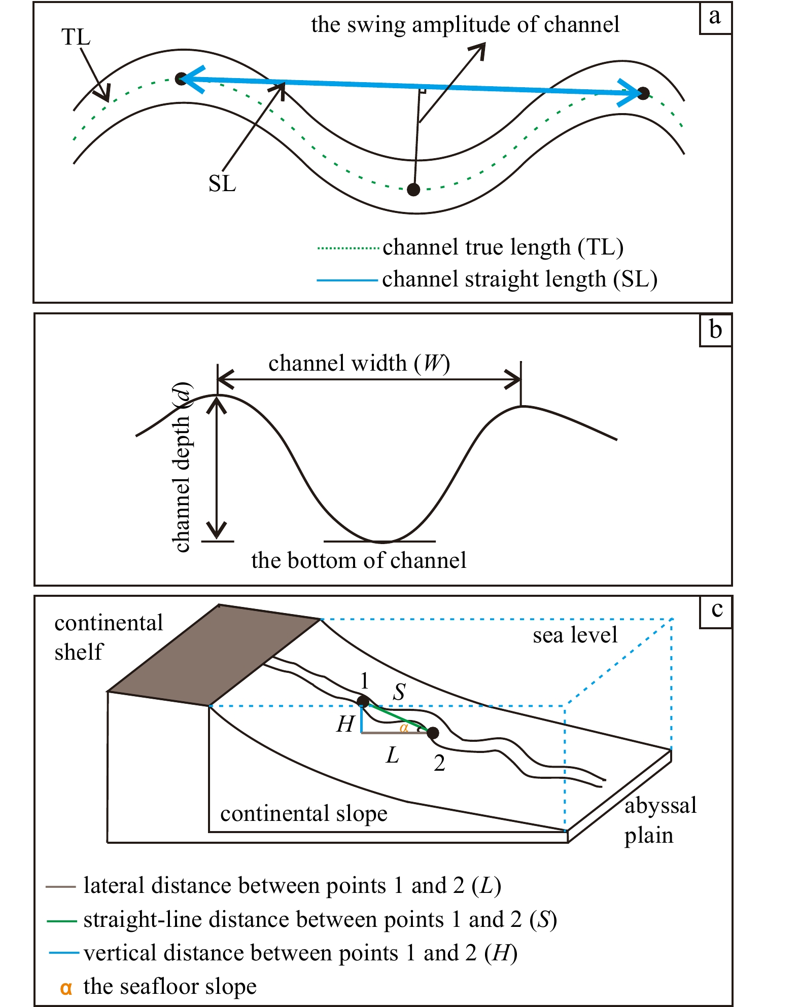
Figure 2. Schematic drawing showing the methods adopted in this study to identify and measure the morphological parameters of the deep-water channel. a. Plan view showing the morphological parameters including the channel true length (TL), channel straight length (SL), and the swing amplitude of channel, in which the sinuosity was calculated as the ratio of the channel TL to the SL. b. Cross-sectional view showing the method adopted to measure the channel’s width and depth. c. Stereogram showing the method used for measuring the slopes of the seafloor. α: seafloor slope gradient, in which the calculation formula of the seafloor slope gradient was as follows: α=arctan (H/L).
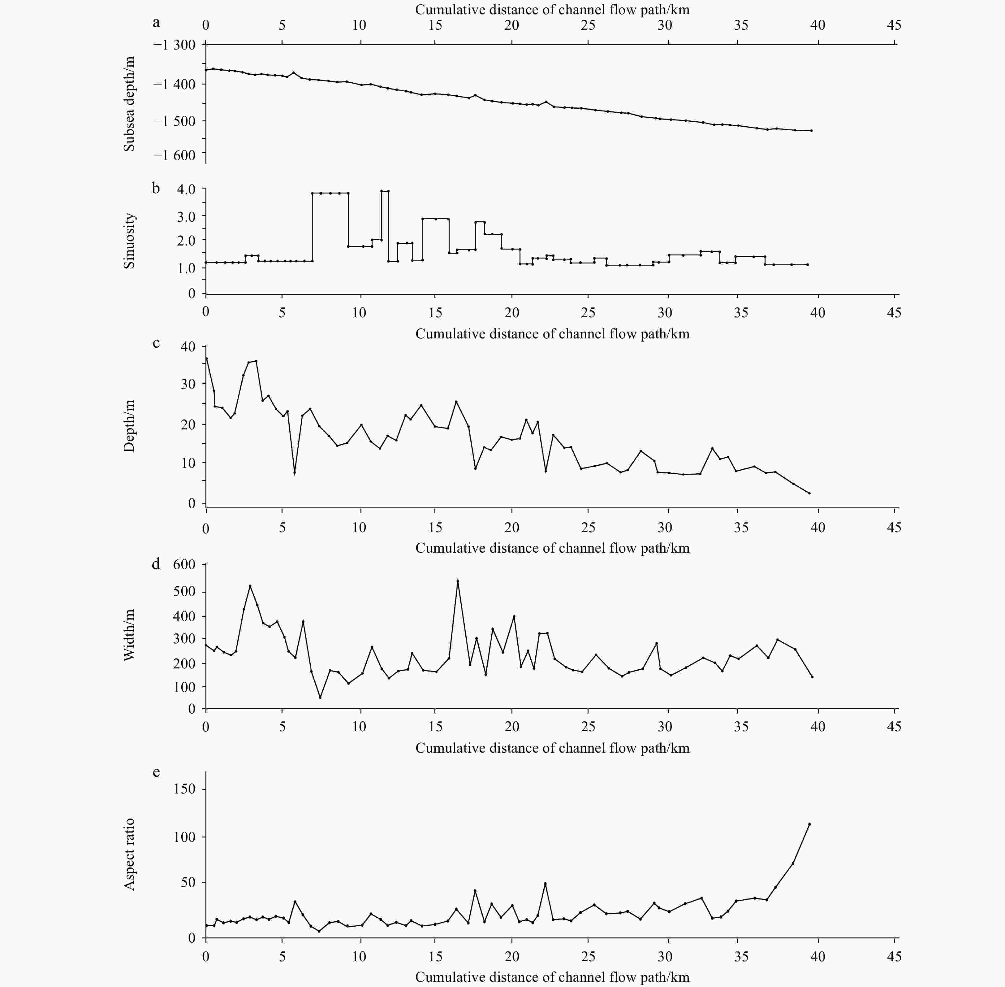
Figure 3. Statistical analysis of the quantitative characteristic parameters of the Channel I in the study area. a. Subsea depth of the Channel I. b. Sinuosity of the Channel I. c. Depth of the Channel I. d. Width of the Channel I. e. Aspect ratio (width/depth) of the Channel I.
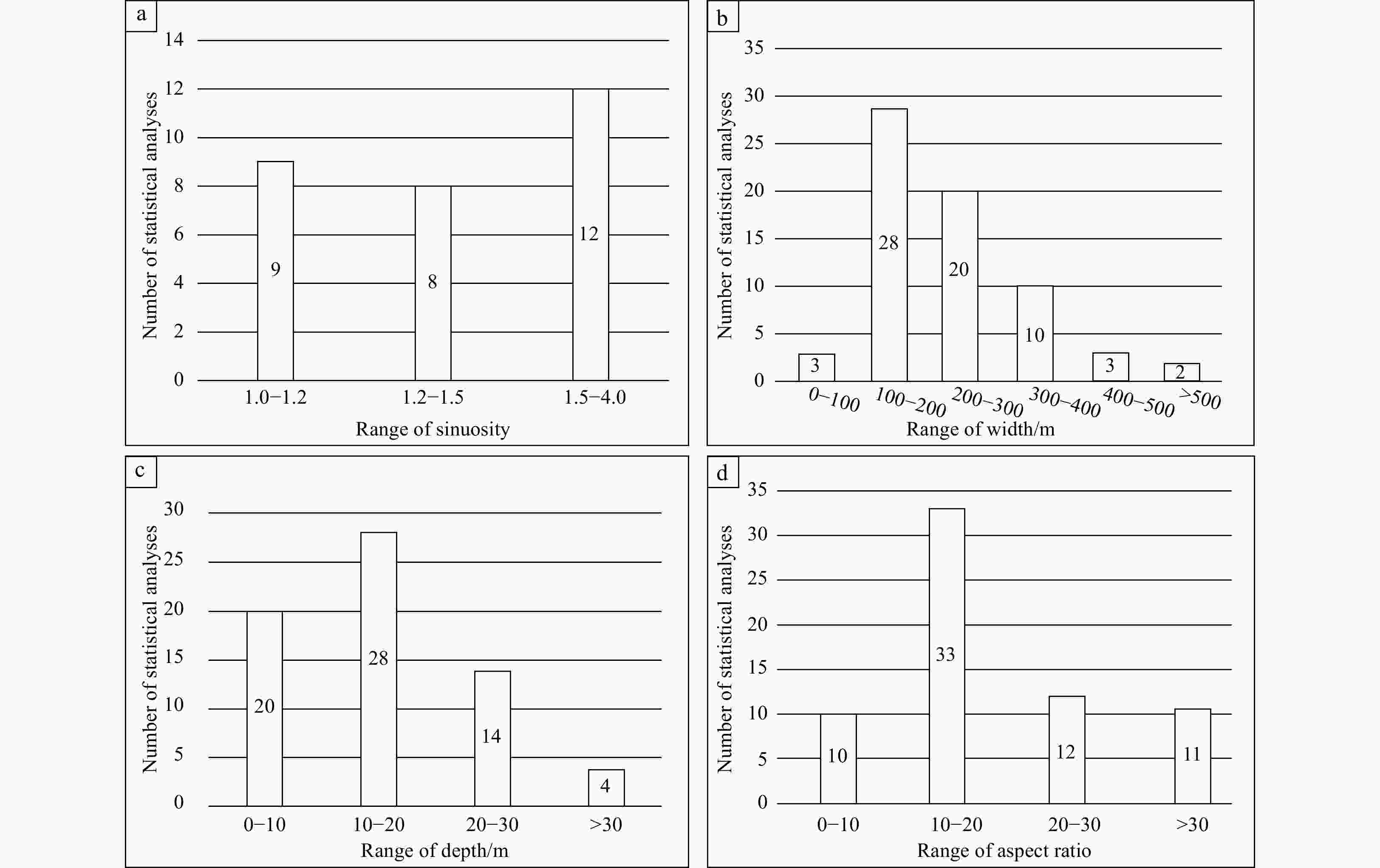
Figure 4. Interval distributions of the quantitative characteristic parameters of the Channel I: statistical analyses of the sinuosity of the Channel I (a), width of the Channel I (b), depth of the Channel I (c), and aspect ratio (width/depth) of the Channel I (d).
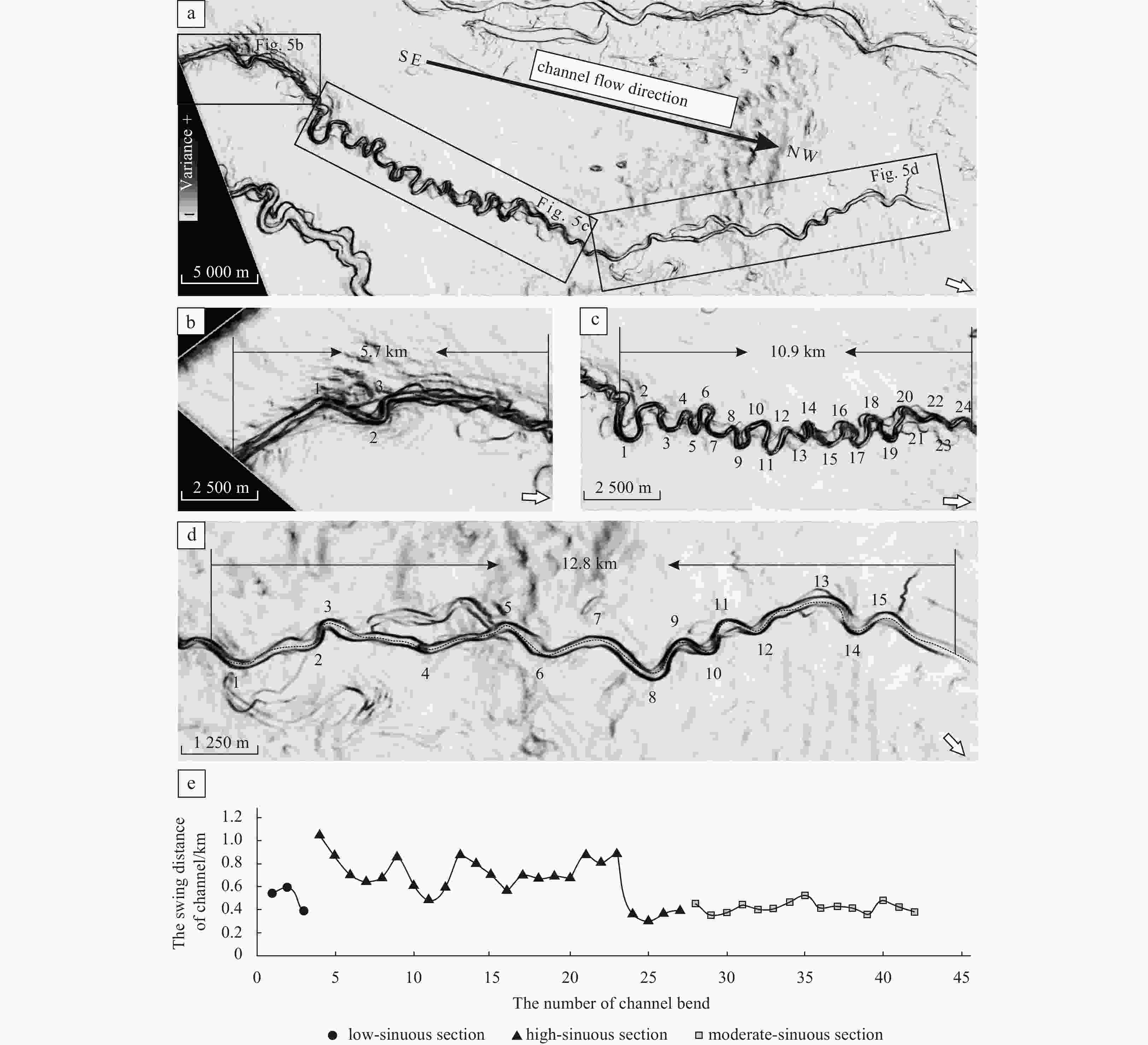
Figure 5. Variance maps showing the different types of geometrical morphology of the Channel I in plan view. a. Overall morphology of the Channel I. b. Low-sinuous channel. c. High-sinuous channel. d. Moderate-sinuous channel. e. Variation in swing amplitude of channel bend. The box presents the different channel forms, and the numbers denote the bends of the Channel I.
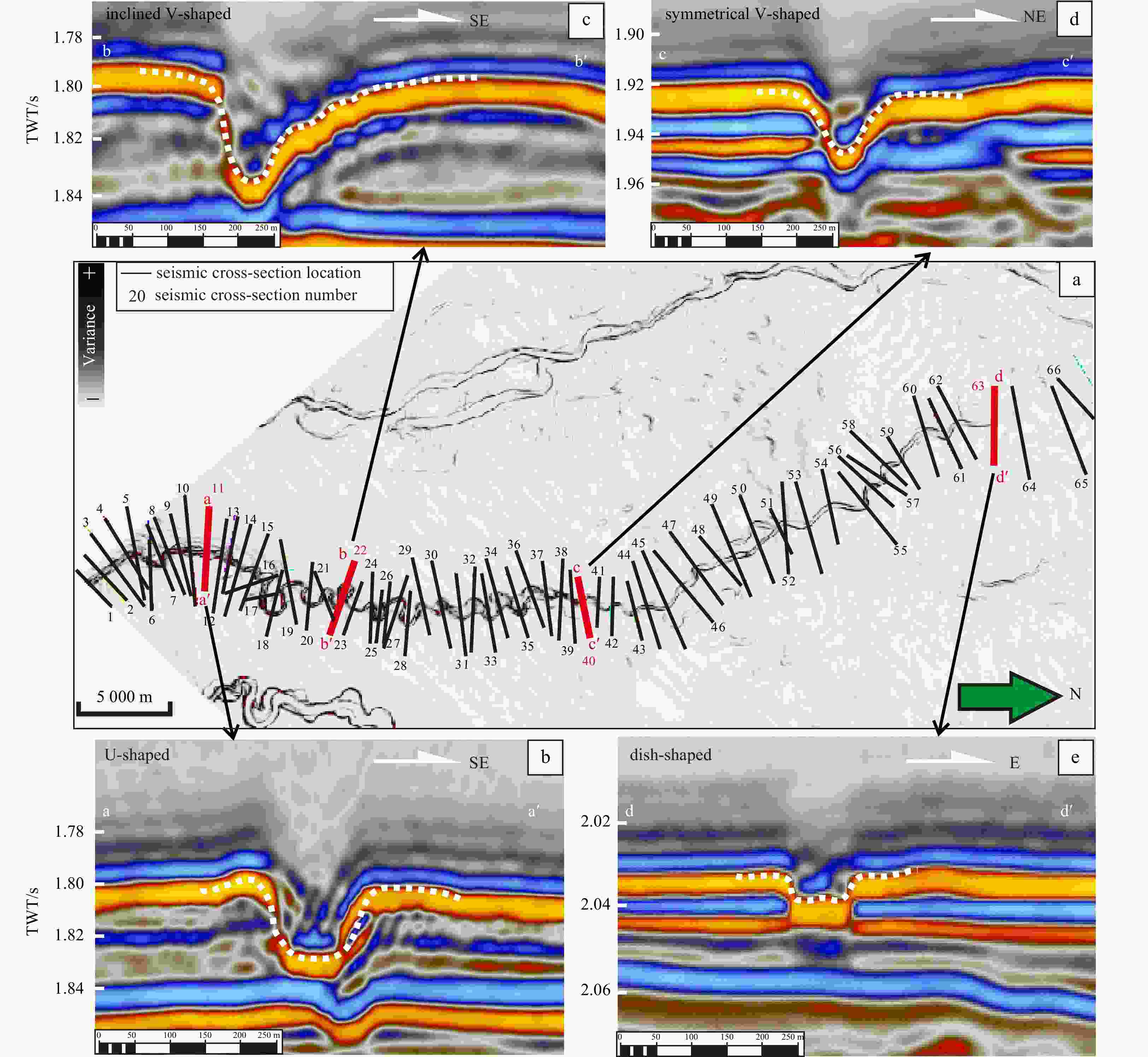
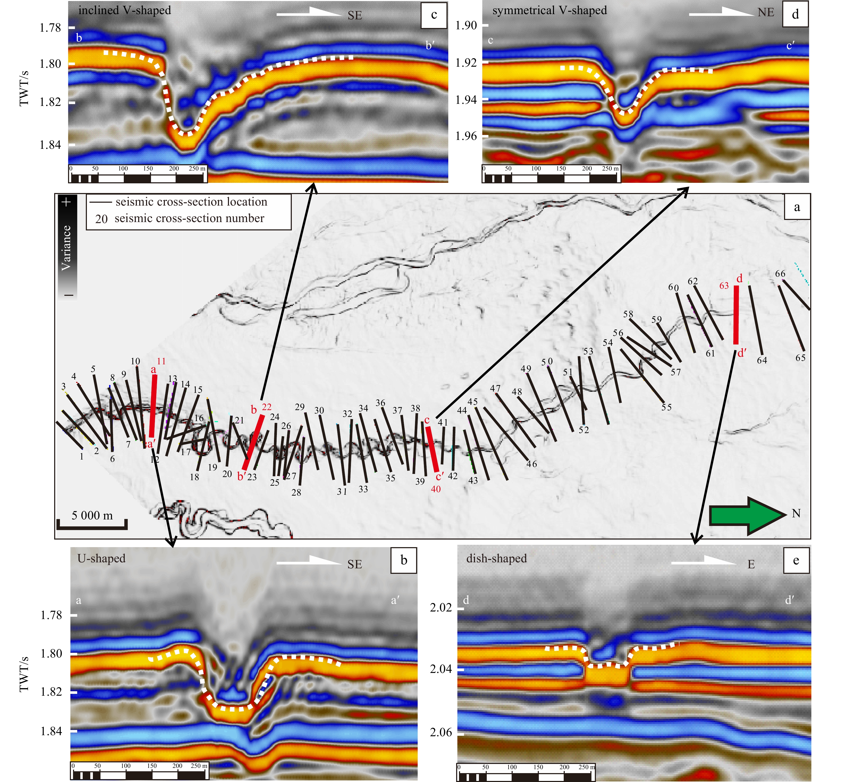
Figure 6. Types of seismic cross-sectional morphologies of the Channel I. a. Locations of the seismic cross-sections are indicated by the solid black lines, the numbers are the channel cross-section labels, and the solid lines represent the various geometrical morphologies of the channel cross-sections: U-shaped (b), inclined V-shaped (c), symmetrical V-shaped (d), and dish-shaped (e).
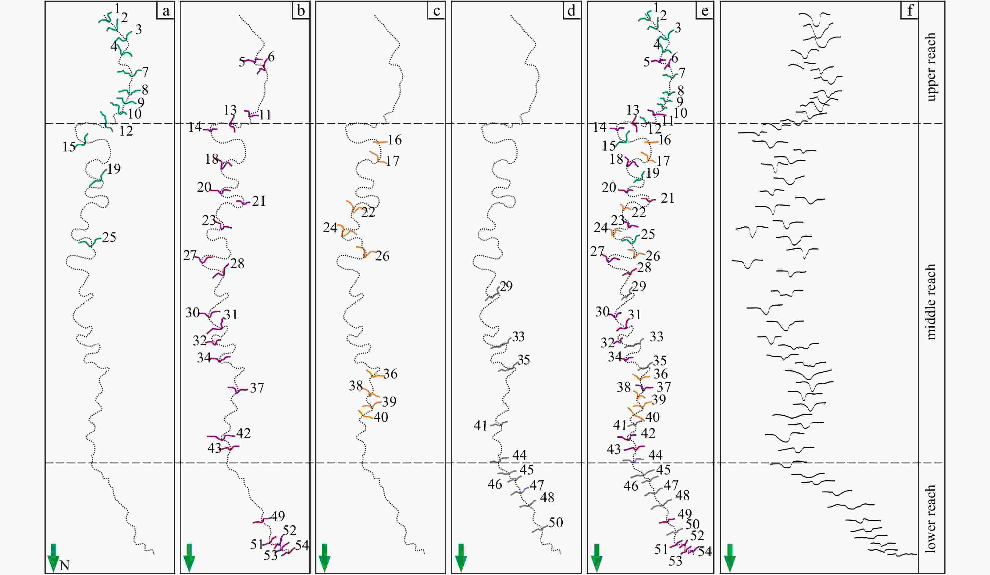
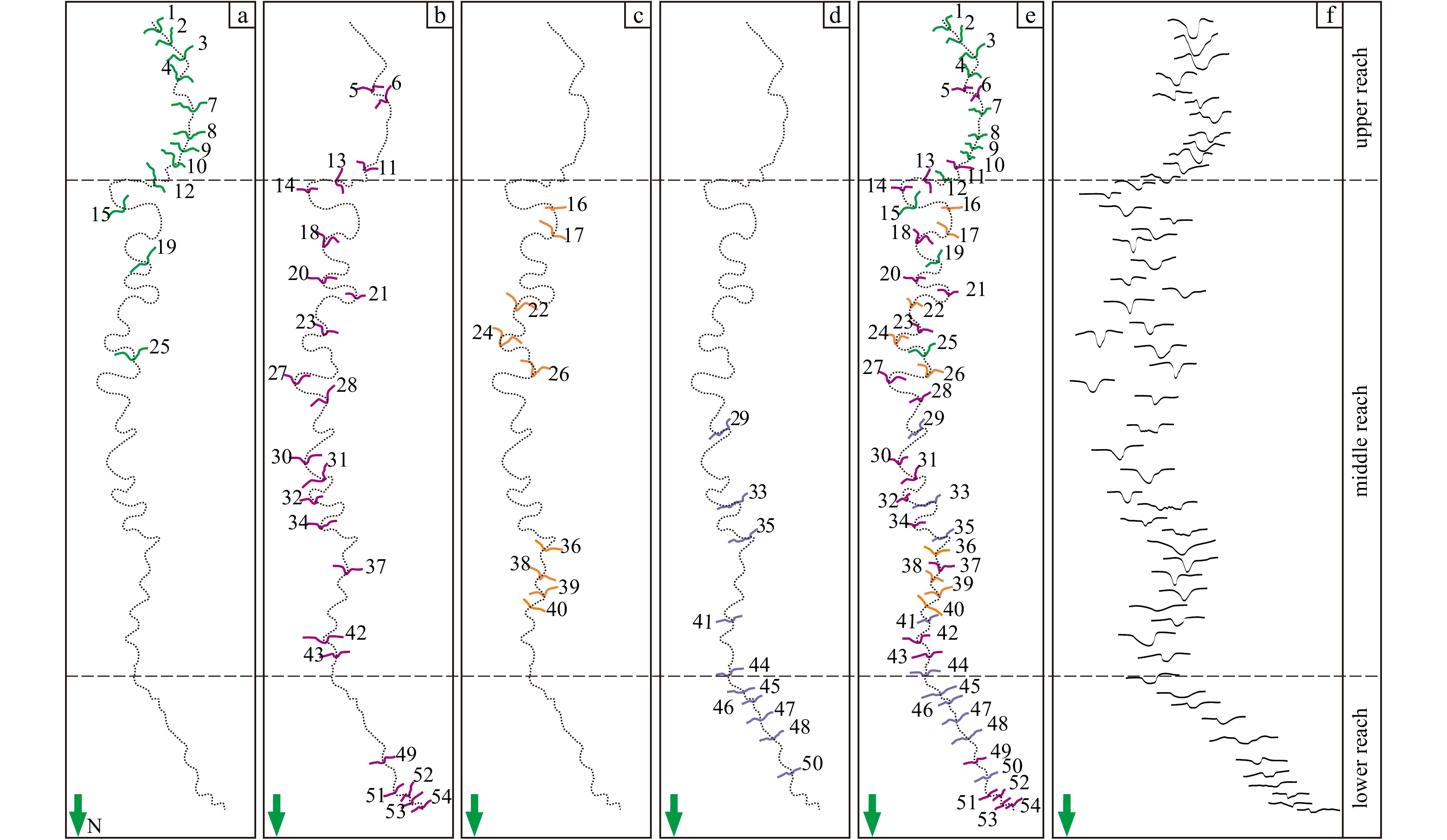
Figure 7. Schematics of the spatial distributions of the different cross-sections of the Channel I. The specific location of four channel cross-sections geometrical morphology, such as U-shaped (a), inclined V-shaped (b), symmetrical V-shaped (c), and dish-shaped (d), in the whole Channel I. e. Spatial distributions of the overall channel cross-sections, where the numbers signify the sequence of the channel cross-sections. f. True morphology of each cross-section. From upstream to downstream, the depth of the Channel I gradually transitions from being narrow and deep to wide and shallow.
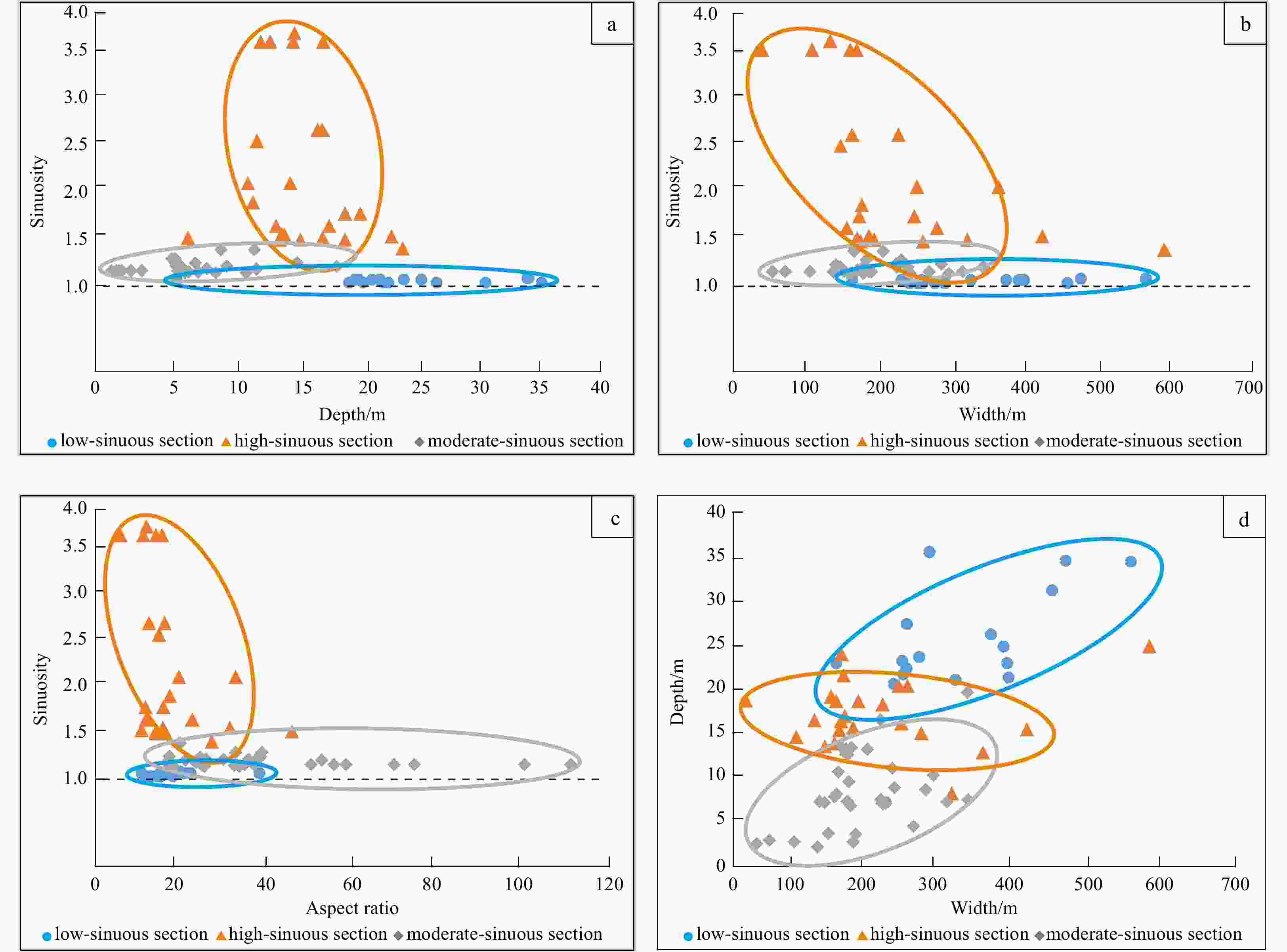
Figure 8. Relationships between the quantitative parameters of the Channel I: relationships between the sinuosity and the depth (a), width (b), aspect ratio (width/depth) (c). d. Relationship between the width and depth of the Channel I.
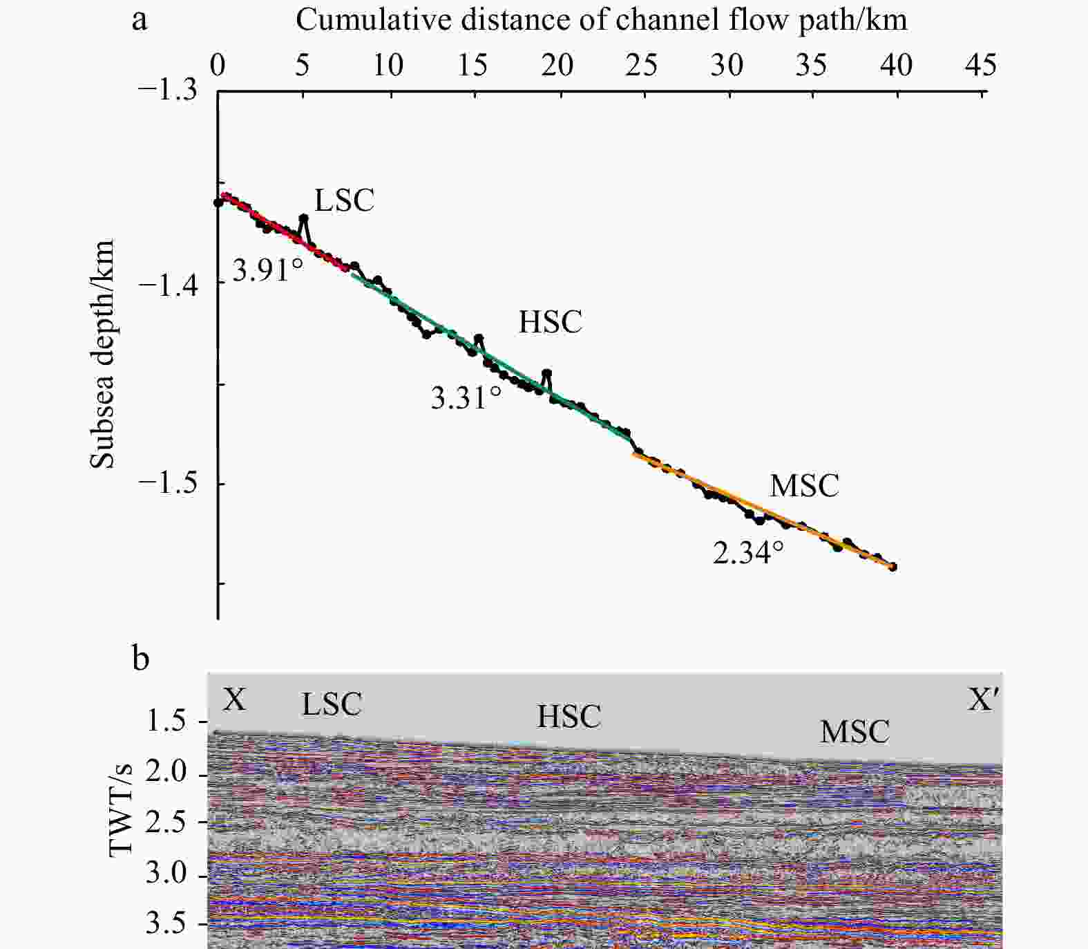
Figure 9. Schematic diagram of the average seafloor slope gradient of the three sections of the Channel I. In a, the seafloor slope gradient of the low-sinuous channel (LSC) is 3.91°, that of the high-sinuous channel (HSC) is 3.31°, and that of the moderate-sinuous channel (MSC) is 2.34°.
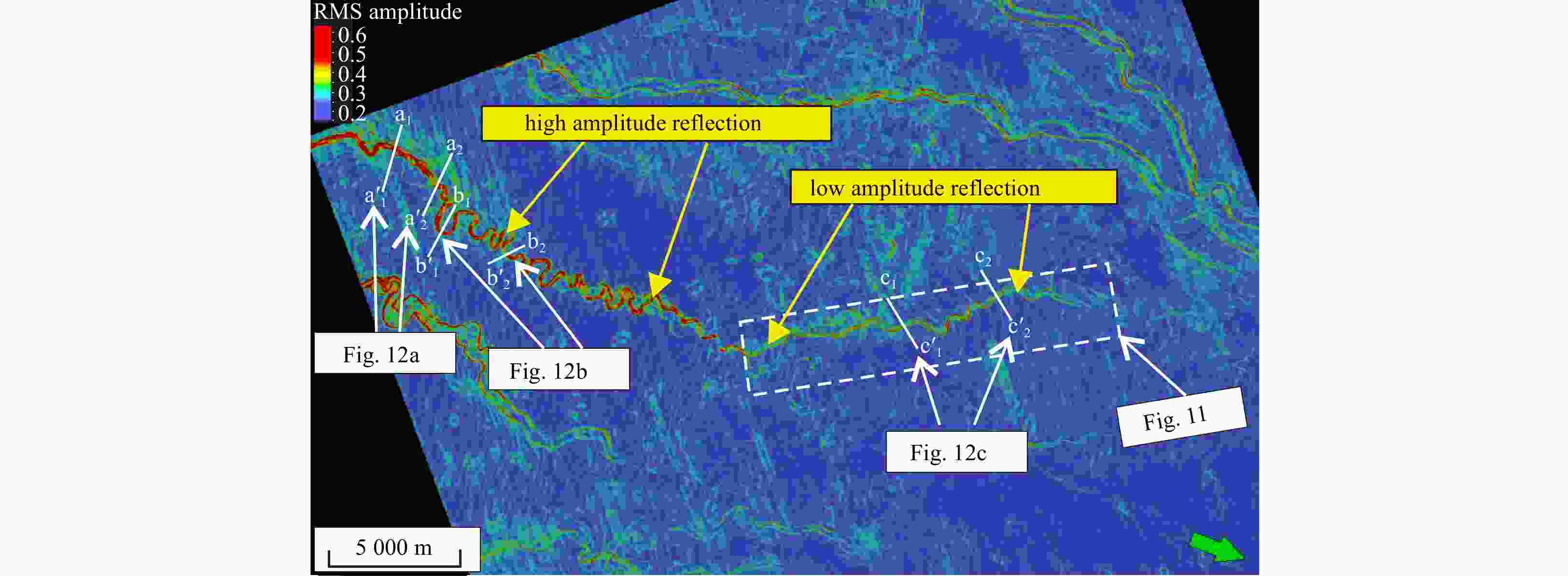
Figure 10. Root mean square (RMS) amplitude attribute map of the Channel I. From upstream to downstream of the channel, the high amplitude reflections change to low amplitude reflections. In the low-sinuous channel and high-sinuous channel, the position of the axis of the channel is marked by high amplitude reflections, while in the moderate-sinuous channel, the axis of the channel is delineated by low amplitude reflections. The red and yellow positions indicate high amplitude reflections, and the green and blue positions indicate low amplitude reflections.

Figure 11. Schematic diagram of a channel crevasse in the moderate-sinuous channel of the Channel I. a. Root mean square (RMS) amplitude attribute map. b. Red-Green-Blue (RGB) colour attribute map. c. Schematic illustration of the formation of a channel crevasse. The black curve represents the present-day channel, the red dotted line represents the paleochannel, and the blue circle represents the crevasse position. The specific location is shown in Fig. 10.

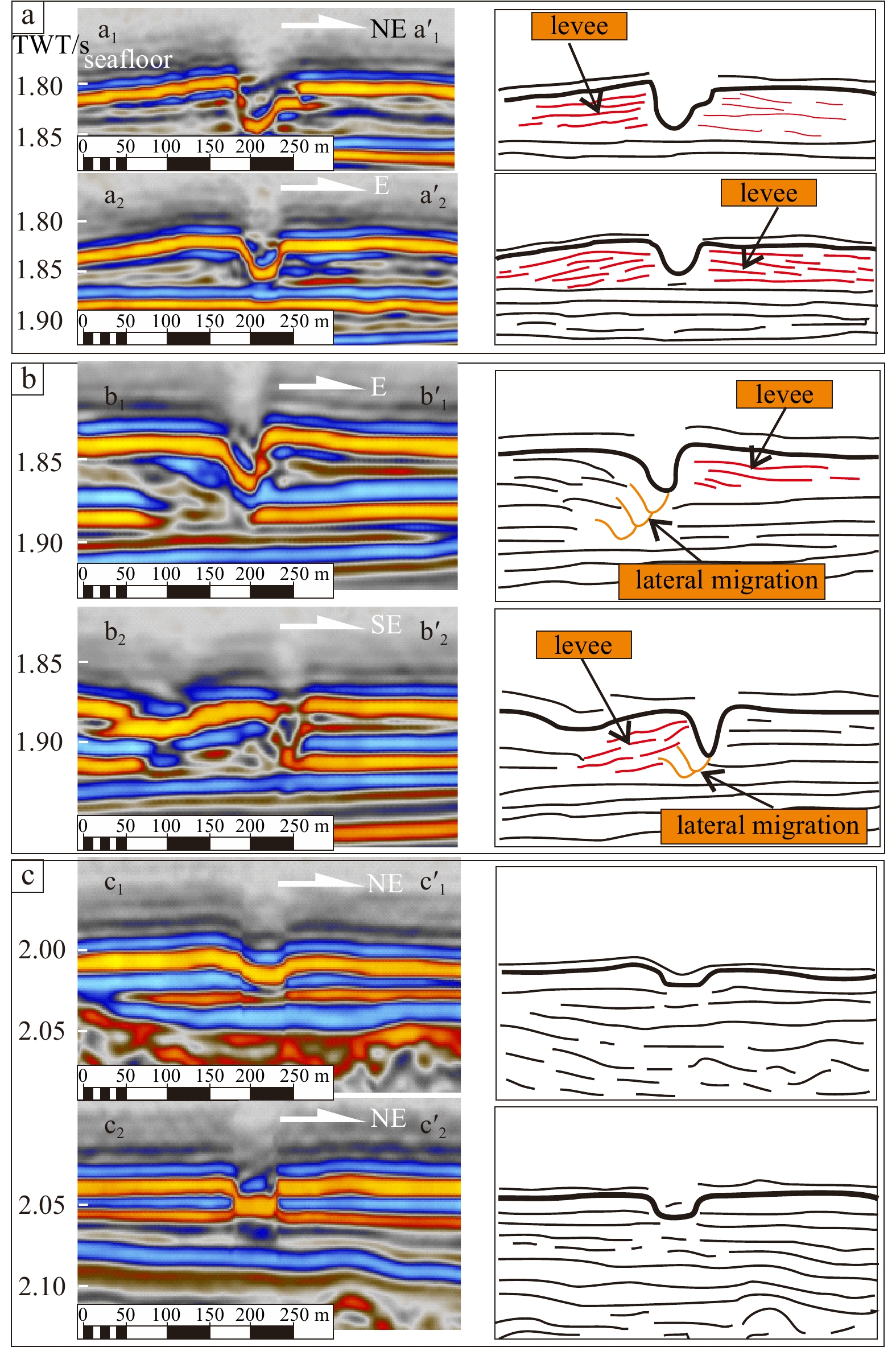
Figure 12. Seismic cross-sections of the levees in each section of the Channel I. Two seismic cross-sections are selected for each part of the Channel I. a. low-sinuous channel: a1−a'1, a2−a'2. b. high-sinuous channel: b1−b'1, b2−b'2. c. moderate-sinuous channel: c1−c'1, c2−c'2. The seismic cross-sections are on the left, and the interpretation diagrams are on the right. The locations of the seismic cross-sections are shown in Fig. 10.
Table 1. Quantitative parameters of the Channel I in different morphological sections
LSC MSC HSC Sinuosity 1.0–1.2 1.2–1.5 1.5–4.0 Width/m Max-W 555.58 336.90 580.58 Min-W 159.05 51.96 37.37 A-W 323.77 196.12 215.43 Depth/m Max-D 35.15 19.66 24.18 Min-D 19.97 8.74 11.97 A-D 25.33 13.23 16.48 Aspect ratio Max-AR 35.43 110.16 43.22 Min-AR 7.11 10.55 2.09 A-AR 14.39 32.52 14.45 $\text{λ} $/m Max- $\text{λ} $ 596.81 525.10 1 050.23 Min- $\text{λ} $ 395.72 357.00 296.10 A- $\text{λ} $ 512.47 424.80 675.49 $\omega $ 0.53 1.17 2.20 Note: A is the average, AR is the aspect ratio, W is the width of the Channel I, D is the depth of the Channel I, $\omega $ is the channel bend frequency,and $\text{λ} $ is the swing amplitude of Channel I. LSC: low-sinuous channel; MSC: moderate-sinuous channel; HSC: high-sinuous channel.  下载: 导出CSV
Table 2. Geometrical morphology characteristics of the Channel I on seismic cross-sections
Seismic facies External geometries Developed location Characteristics Seismic cross-section Interpretation a U-shaped middle and upper position of the channel The gravity flow flowing through the channel has large scale, strong energy and strong undercut erosion ability. “Gull wing” levee structure is mostly developed in this area. 

b inclined V-shaped bend position of the channel The scale of gravity flow decreases, the fluid energy decreases, and the undercutting erosion ability of the fluid is strong. Asymmetric levee structures are mostly developed in the channel in this area, and the concave bank slope of the levee is steep and the convex bank slope is slow. 

c symmetrical V-shaped the straight section of the channel The scale of gravity flow is small, the fluid has medium to weak energy intensity, and the undercut erosion ability of the fluid is weakened. Symmetrical V-shaped cross-sections are mostly developed in relatively straight channel sections. 

d dish-shaped terminal position of the channel The scale of gravity flow is very small and the fluid energy is weak. The channel is in a non-restrictive environment. The levee structure is basically undeveloped, and the bottom of the channel is relatively flat. 
 下载: 导出CSV
-
Abreu V, Sullivan M, Pirmez C, et al. 2003. Lateral accretion packages (LAPS): an important reservoir element in deep water sinuous channels. Marine and Petroleum Geology, 20(6–8): 631–648 Alpak F O, Barton M D, Naruk S J. 2013. The impact of fine-scale turbidite channel architecture on deep-water reservoir performance. AAPG Bulletin, 97(2): 251–284. doi: 10.1306/04021211067 Babonneau N, Savoye B, Cremer M, et al. 2002. Morphology and architecture of the present canyon and channel system of the Zaire deep-sea fan. Marine and Petroleum Geology, 19(4): 445–467. doi: 10.1016/S0264-8172(02)00009-0 Babonneau N, Savoye B, Cremer M, et al. 2010. Sedimentary architecture in meanders of a submarine channel: Detailed study of the present Congo Turbidite channel (Zaiango Project). Journal of Sedimentary Research, 80(10): 852–866. doi: 10.2110/jsr.2010.078 Biscara L, Mulder T, Martinez P, et al. 2011. Transport of terrestrial organic matter in the Ogooué deep sea turbidite system (Gabon). Marine and Petroleum Geology, 28(5): 1061–1072. doi: 10.1016/j.marpetgeo.2010.12.002 Carter R M, Norris R J. 1976. Cainozoic history of southern New Zealand: an accord between geological observations and plate-tectonic predictions. Earth and Planetary Science Letters, 31(1): 85–94. doi: 10.1016/0012-821X(76)90099-6 Clark J D, Kenyon N H, Pickering K T. 1992. Quantitative analysis of the geometry of submarine channels: implications for the classification of submarine fans. Geology, 20(7): 633–636. doi: 10.1130/0091-7613(1992)020<0633:QAOTGO>2.3.CO;2 Clark J D, Pickering K T. 1996. Architectural elements and growth patterns of submarine channels: application to hydrocarbon exploration. AAPG Bulletin, 80(2): 194–220 Dai Zhijun, Liu James T, Fu Gui, et al. 2013. A thirteen-year record of bathymetric changes in the North Passage, Changjiang (Yangtze) estuary. Geomorphology, 187: 101–107. doi: 10.1016/j.geomorph.2013.01.004 Dai Zhijun, Mei Xuefei, Darby S E, et al. 2018. Fluvial sediment transfer in the Changjiang (Yangtze) river-estuary depositional system. Journal of Hydrology, 566: 719–734. doi: 10.1016/j.jhydrol.2018.09.019 D’Alpaos A, Ghinassi M, Finotello A, et al. 2017. Tidal meander migration and dynamics: a case study from the Venice Lagoon. Marine and Petroleum Geology, 87: 80–90. doi: 10.1016/j.marpetgeo.2017.04.012 Deptuck M E, Steffens G S, Barton M, et al. 2003. Architecture and evolution of upper fan channel-belts on the Niger Delta slope and in the Arabian Sea. Marine and Petroleum Geology, 20(6–8): 649–676 Deptuck M E, Sylvester Z, Pirmez C, et al. 2007. Migration-aggradation history and 3-D seismic geomorphology of submarine channels in the Pleistocene Benin-major Canyon, western Niger Delta slope. Marine and Petroleum Geology, 24(6–9): 406–433 Dott R H. 1963. Dynamics of subaqueous gravity depositional processes. AAPG Bulletin, 47(1): 104–128 Gabet E J. 1998. Lateral migration and bank erosion in a saltmarsh tidal channel in San Francisco Bay, California. Estuaries, 21(4): 745–753. doi: 10.2307/1353278 Gamboa D, Alves T M. 2015. Spatial and dimensional relationships of submarine slope architectural elements: A seismic-scale analysis from the Espírito Santo Basin (SE Brazil). Marine and Petroleum Geology, 64: 43–57. doi: 10.1016/j.marpetgeo.2015.02.035 Gee M J R, Gawthorpe R L. 2006. Submarine channels controlled by salt tectonics: examples from 3D seismic data offshore Angola. Marine and Petroleum Geology, 23(4): 443–458. doi: 10.1016/j.marpetgeo.2006.01.002 Gee M J R, Gawthorpe R L, Bakke K, et al. 2007. Seismic geomorphology and evolution of submarine channels from the Angolan continental margin. Journal of Sedimentary Research, 77(5): 433–446. doi: 10.2110/jsr.2007.042 Giba M, Walsh J J, Nicol A, et al. 2013. Investigation of the spatio-temporal relationship between normal faulting and arc volcanism on million-year time scales. Journal of the Geological Society, 170(6): 951–962. doi: 10.1144/jgs2012-121 Harishidayat D, Omosanya K O, Johansen S E. 2015. 3D seismic interpretation of the depositional morphology of the middle to late Triassic fluvial system in eastern Hammerfest Basin, Barents Sea. Marine and Petroleum Geology, 68: 470–479. doi: 10.1016/j.marpetgeo.2015.09.007 Higgs K E, Arnot M J, Browne G H, et al. 2010. Reservoir potential of late cretaceous terrestrial to shallow marine sandstones, Taranaki Basin, New Zealand. Marine and Petroleum Geology, 27(9): 1849–1871. doi: 10.1016/j.marpetgeo.2010.08.002 Hudson P F, Kesel R H. 2000. Channel migration and meander-bend curvature in the lower Mississippi River prior to major human modification. Geology, 28(6): 531–534. doi: 10.1130/0091-7613(2000)28<531:CMAMCI>2.0.CO;2 Janocko M, Nemec W, Henriksen S, et al. 2013. The diversity of deep-water sinuous channel belts and slope valley-fill complexes. Marine and Petroleum Geology, 41: 7–34. doi: 10.1016/j.marpetgeo.2012.06.012 Khripounoff A, Vangriesheim A, Babonneau N, et al. 2003. Direct observation of intense turbidity current activity in the Zaire submarine valley at 4000 m water depth. Marine Geology, 194(3–4): 151–158 King P R. 2000. New Zealand’s changing configuration in the last 100 million years: plate tectonics, basin development, and depositional setting. In: 2000 New Zealand Petroleum Conference Proceedings. Wellington: Crown Minerals, Ministry of Commerce Wellington, New Zealand King P R, Thrasher G P. 1996. Cretaceous-Cenozoic geology and petroleum systems of the Taranaki Basin, New Zealand [dissertation]. Lower Hutt: Institute of Geological & Nuclear Sciences Kolla V. 2007. A review of sinuous channel avulsion patterns in some major deep-sea fans and factors controlling them. Marine and Petroleum Geology, 24(6–9): 450–469 Labourdette R. 2007. Integrated three-dimensional modeling approach of stacked turbidite channels. AAPG Bulletin, 91(11): 1603–1618. doi: 10.1306/06210706143 Li Quan, Wu Wei, Yu Shui, et al. 2017a. The application of three-dimensional seismic spectral decomposition and semblance attribute to characterizing the Deepwater channel depositional elements in the Taranaki Basin of New Zealand. Acta Oceanologica Sinica, 36(9): 79–86. doi: 10.1007/s13131-017-1113-0 Li Lei, Yan Rui, Li Ningtao, et al. 2015. Characteristics and origin of deep-water channels in Rio Muni Basin, West Africa. Geoscience (in Chinese), 29(1): 80–88 Li Quan, Yu Shui, Wu Wei, et al. 2017b. Detection of a deep-water channel in 3D seismic data using the sweetness attribute and seismic geomorphology: a case study from the Taranaki Basin, New Zealand. New Zealand Journal of Geology and Geophysics, 60(3): 199–208. doi: 10.1080/00288306.2017.1307230 Li Lei, Zou Yun, Zhang Peng, et al. 2019. Quantitative analysis of the geometry of sinuous submarine channels: a case from the Rio Muni Basin of Equatorial Guinea. Marine Geology Frontiers (in Chinese), 35(10): 23–35 Liu Xinying, Yu Shui, Hu Xiaolin, et al. 2012. Quantitative relation between the gradient and sinuosity of Deepwater channel and its control: a case study in the Rio Muni Basin, West Africa. Journal of Jilin University (Earth Science Edition) (in Chinese), 42(S1): 127–134 Lowe D R, Graham S A, Malkowski M A, et al. 2019. The role of avulsion and splay development in deep-water channel systems: sedimentology, architecture, and evolution of the deep-water Pliocene Godavari “A” channel complex, India. Marine and Petroleum Geology, 105: 81–99. doi: 10.1016/j.marpetgeo.2019.04.010 Malkowski M A, Jobe Z R, Sharman G R, et al. 2018. Down-slope facies variability within deep-water channel systems: insights from the Upper Cretaceous Cerro Toro Formation, southern Patagonia. Sedimentology, 65(6): 1918–1946. doi: 10.1111/sed.12452 Masalimova L U, Lowe D R, Sharman G R, et al. 2016. Outcrop characterization of a submarine channel-lobe complex: the lower mount messenger formation, Taranaki Basin, New Zealand. Marine and Petroleum Geology, 71: 360–390. doi: 10.1016/j.marpetgeo.2016.01.004 Mayall M, Jones E, Casey M. 2006. Turbidite channel reservoirs-Key elements in facies prediction and effective development. Marine and Petroleum Geology, 23(8): 821–841. doi: 10.1016/j.marpetgeo.2006.08.001 McHargue T, Pyrcz M J, Sullivan M D, et al. 2011. Architecture of turbidite channel systems on the continental slope: patterns and predictions. Marine and Petroleum Geology, 28(3): 728–743. doi: 10.1016/j.marpetgeo.2010.07.008 Mei Xuefei, Dai Zhijun, Wei Wen, et al. 2018. Secular bathymetric variations of the North Channel in the Changjiang (Yangtze) Estuary, China, 1880–2013: causes and effects. Geomorphology, 303: 30–40. doi: 10.1016/j.geomorph.2017.11.014 Mutti E, Normark W R. 1987. Comparing examples of modern and ancient turbidite systems: problems and concepts. In: Leggett J K, Zuffa G G, eds. Marine Clastic Sedimentology. Dordrecht: Springer, 1–38 Niyazi Y, Eruteya O E, Omosanya K O, et al. 2018. Seismic geomorphology of submarine channel-belt complexes in the Pliocene of the Levant Basin, offshore central Israel. Marine Geology, 403: 123–138. doi: 10.1016/j.margeo.2018.05.007 Peakall J, McCaffrey B, Kneller B. 2000. A process model for the evolution, morphology, and architecture of sinuous submarine channels. Journal of Sedimentary Research, 70(3): 434–448. doi: 10.1306/2DC4091C-0E47-11D7-8643000102C1865D Pichevin L, Bertrand P, Boussafir M, et al. 2004. Organic matter accumulation and preservation controls in a deep sea modern environment: an example from Namibian slope sediments. Organic Geochemistry, 35(5): 543–559. doi: 10.1016/j.orggeochem.2004.01.018 Pirmez C, Imran J. 2003. Reconstruction of turbidity currents in Amazon channel. Marine and Petroleum Geology, 20(6–8): 823–849 Posamentier H W. 2003. Depositional elements associated with a basin floor channel-levee system: case study from the Gulf of Mexico. Marine and Petroleum Geology, 20(6–8): 677–690 Qin Yongpeng, Alves T M, Constantine J, et al. 2016. Quantitative seismic geomorphology of a submarine channel system in SE Brazil (Espírito Santo Basin): scale comparison with other submarine channel systems. Marine and Petroleum Geology, 78: 455–473. doi: 10.1016/j.marpetgeo.2016.09.024 Reimchen A P, Hubbard S M, Stright L, et al. 2016. Using sea-floor morphometrics to constrain stratigraphic models of sinuous submarine channel systems. Marine and Petroleum Geology, 77: 92–115. doi: 10.1016/j.marpetgeo.2016.06.003 Rotzien J R. 2013. Processes of sedimentation, stratigraphic architecture, and provenance of deep-water depositional systems: the upper Miocene Upper Mount messenger formation, Taranaki Basin, New Zealand and Pliocene Repetto and Pico formations, Ventura Basin, California [dissertation]. Stanford: Stanford University, 218 Rotzien J R, Lowe D R, King P R, et al. 2014. Stratigraphic architecture and evolution of a deep-water slope channel-levee and overbank apron: the Upper Miocene Upper Mount Messenger Formation, Taranaki Basin. Marine and Petroleum Geology, 52: 22–41. doi: 10.1016/j.marpetgeo.2014.01.006 Stagpoole V M, Hill M, Thornton S, et al. 2002. New Zealand Basin development and depositional systems evolution: quantification and Visualisation. In: 2002 New Zealand Petroleum Conference Proceedings. Auckland: GNS Science, 351–362 Straub K M, Mohrig D, Buttles J, et al. 2011. Quantifying the influence of channel sinuosity on the depositional mechanics of channelized turbidity currents: a laboratory study. Marine and Petroleum Geology, 28(3): 744–760. doi: 10.1016/j.marpetgeo.2010.05.014 Sutherland R. 1999. Basement geology and tectonic development of the greater New Zealand region: an interpretation from regional magnetic data. Tectonophysics, 308(3): 341–362. doi: 10.1016/S0040-1951(99)00108-0 Tek D E, McArthur A D, Poyatos-Moré M, et al. 2022. Controls on the architectural evolution of deep-water channel overbank sediment wave fields: insights from the Hikurangi Channel, offshore New Zealand. New Zealand Journal of Geology and Geophysics, 65(1): 141–178. doi: 10.1080/00288306.2021.1978509 Uruski C I. 2008. Deepwater Taranaki, New Zealand: structural development and petroleum potential. Exploration Geophysics, 39(2): 94–107. doi: 10.1071/EG08013 Uruski C I. 2010. New Zealand’s Deepwater frontier. Marine and Petroleum Geology, 27(9): 2005–2026. doi: 10.1016/j.marpetgeo.2010.05.010 Wynn R B, Cronin B T, Peakall J. 2007. Sinuous deep-water channels: Genesis, geometry and architecture. Marine and Petroleum Geology, 24(6–9): 341–387 Xu Jie, Snedden J W, Galloway W E, et al. 2017. Channel-belt scaling relationship and application to early Miocene source-to-sink systems in the Gulf of Mexico Basin. Geosphere, 13(1): 179–200. doi: 10.1130/GES01376.1 Yao Yue, Zhou Jiangyu, Lei Zhenyu, et al. 2018. High restriction seismic facies and inner structural segmentation features of the central canyon channel systems in Xisha trough basin. Acta Sedimentologica Sinica (in Chinese), 36(4): 787–795 Zhao Xiaoming, Liu Li, Tan Chengpeng, et al. 2018a. Styles of submarine-channel architecture and its controlling factors: a case study from the Niger Delta Basin slope. Journal of Palaeogeography (in Chinese), 20(5): 825–840 Zhao Xiaoming, Qi Kun, Liu Li, et al. 2018b. Development of a partially-avulsed submarine channel on the Niger Delta continental slope: architecture and controlling factors. Marine and Petroleum Geology, 95: 30–49. doi: 10.1016/j.marpetgeo.2018.04.015 Zhou Xiaoyan, Dai Zhijun, Mei Xuefei. 2020. The multi-decadal morphodynamic changes of the mouth bar in a mixed fluvial-tidal estuarine channel. Marine Geology, 429: 106311. doi: 10.1016/j.margeo.2020.106311 Zucker E, Gvirtzman Z, Steinberg J, et al. 2017. Diversion and morphology of submarine channels in response to regional slopes and localized salt tectonics, Levant Basin. Marine and Petroleum Geology, 81: 98–111. doi: 10.1016/j.marpetgeo.2017.01.002 -


 点击查看大图

计量
- 文章访问数: 436
- HTML全文浏览量: 143
- PDF下载量: 44
- 被引次数: 0